Design and Construction of Tachometer Using Arduino Microcontroller Circuit Diagram DIY Tachometer (RPM Meter): In this project I will show you how a 3€ IR distance sensor works and how we can use it to build a proper DIY tachometer that functions properly. Step 3: Create the Circuit! Here you can find the schematic with reference pictures of my finished board design. Use them to create your own! Step 4: Upload the Code The Tachometer is an RPM counter which counts the no. of rotation per minute. There are two types of tachometer one mechanical and another one is digital. Here we are going to design an Arduino-based digital tachometer using an IR sensor module to detect objects for count rotation of any rotating body.

A digital tachometer circuit is a device that measures the rotational speed of a motor or other rotating object and displays the results in a digital format. To build a digital tachometer circuit, there are several key components that are required. Follow this step-by-step guide to successfully create your own digital tachometer. 1. Gather

DIY Tachometer (RPM Meter) : 5 Steps Circuit Diagram
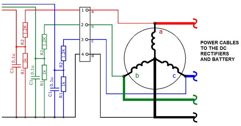
P rinciple Behind the Circuit. The basic principle behind the Contactless Digital Tachometer involves a simple embedded system with a sensor, a controller and an actuator. The sensor used here is Infrared (IR) transmitter - receiver pair, the controller used is the 8051 Microcontroller loaded with a compiled code and the actuator is a display device, for displaying the speed of the motor. This article is about a contactless digital tachometer using arduino. The speed of the motor can be also controlled using the same circuit. The RPM and all the other informations are displayed on a 16×2 LCD screen. The circuit diagram of the digital tachometer using arduino is shown below. Circuit diagram.
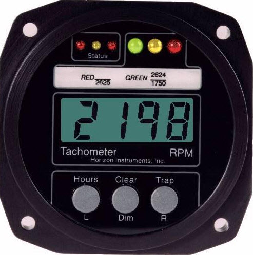
Calibration and Testing: Fine-Tuning Your Tachometer. After building your circuit and writing the code, it's time to calibrate and test your digital tachometer. 1. Calibration: Connect your tachometer to your engine. Start the engine and let it idle. Compare the reading on your digital tachometer to a known RPM source. Step 2: Design the circuit. Next, you will need to design the circuit for your digital tachometer. Start by connecting the sensor to the microcontroller, which will be responsible for processing the signals and calculating the motor's speed. Connect the LCD display to the microcontroller to show the speed readings. Digital Tachometer RPM Display. Unlike analog tachometers, digital tachometers have the memory to store readings. They also utilize digital displays like LCD or LED displays to indicate current readings. You can use these tachometers for high-precision measurement applications and statistical operations.