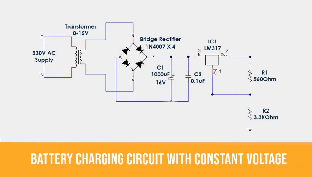
Battery Charger Circuits Circuit Diagram The battery charger circuit consists of several components, including a transformer, rectifier, voltage regulator, and charging controller. Each component works together to ensure that the battery receives the correct voltage and current levels for safe charging. Various charger types include trickle chargers, smart chargers, and fast chargers

Learn how to charge a Li-Ion battery using simple ICs like LM317, NE555 and LM324. See four different designs with advantages, disadvantages and tips for each circuit.
PDF Battery Charging Circuit Diagram
Learn about the electrochemistry, optimum charging cycle, and fast charging techniques for lithium ion (Li-ion) batteries. Find out the advantages, drawbacks, and trade-offs of accelerating charging rates for portable electronics.

Learn about charging methods, end-of-charge-detection techniques, and charger circuits for Ni-Cd, Ni-MH, and Li-Ion batteries. Compare slow charge, fast charge, and possible cell damage for different battery types.

How Battery Charger Circuit Works: Basics, Design, And Diagrams ... Circuit Diagram
Learn how to charge different types of batteries safely and efficiently with various methods and circuits. Compare CCR, NVDC, and HPB charging technologies for NiMH, NiCd, Li-ion, and PbA batteries. A charging circuit is an electronic circuit that is designed to recharge a battery or other energy storage device by converting an external power source (such as AC power from a wall outlet or DC power from a solar panel) into the appropriate voltage and current needed to charge the battery. The official Battery Charging 1.2 standard allows 1.5A on DCP and CDP ports. DCP ports are dumb chargers that connect D+ and D- with less than 200 Ohms. I wish there were a charger circuit as
